Jan 26, 2026 • Tamas Balogh
AutoCAD automation in Design Automation
How we automated PDF drawing exports of CADWorx Structure entities using AutoCAD Design Automation; solving challenges from proxy entities and XData parsing to 3D-to-paper-space annotations and precise viewport placement.
What needed to be solved?
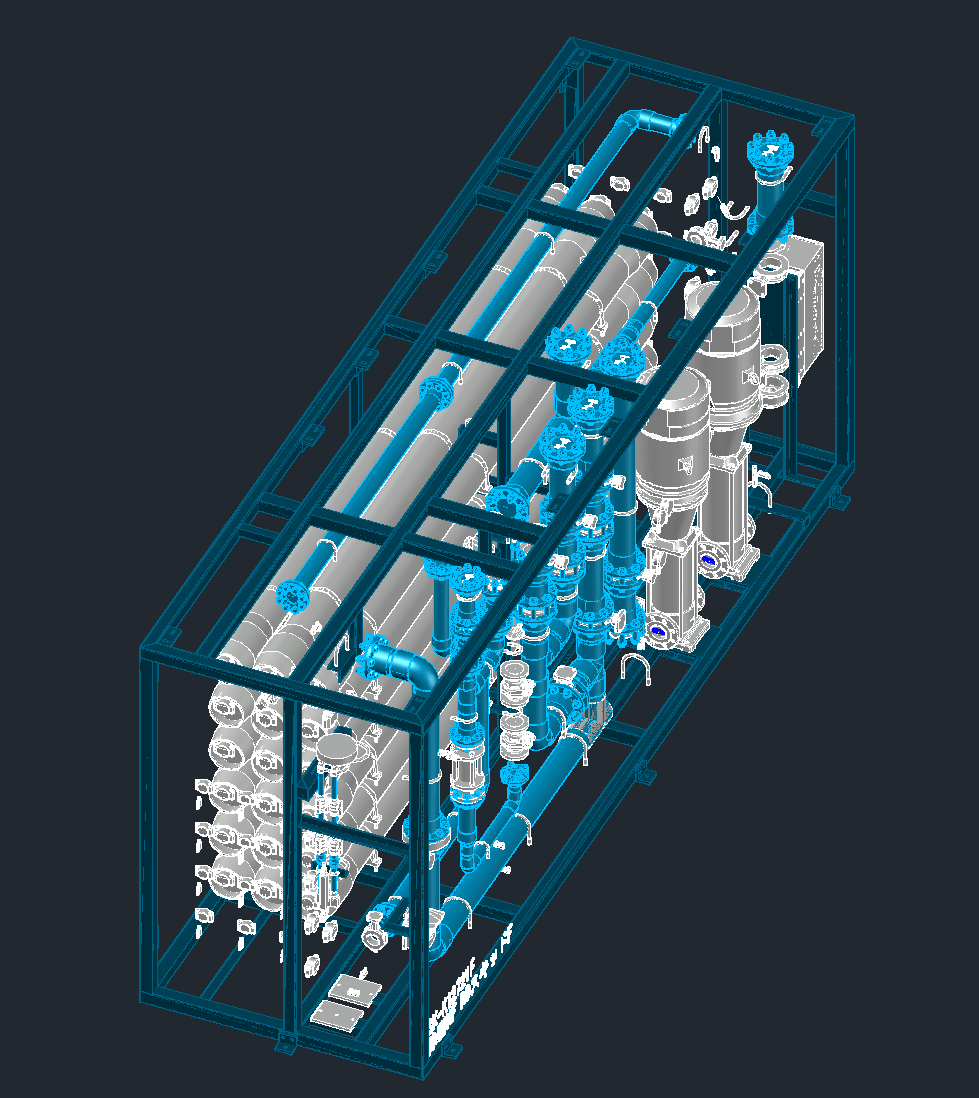
Input geometry before CAD cleanup and processing.
CADWorx Structure is an AutoCAD plugin used to model custom structural entities around water-treatment equipment. Designers create cubical steel frames around piping/equipment sections commonly called skids. Each steel skid has a skid designation / skid number stored on all entities that belong to that skid.
When the client prepares 3D drawings for manufacturing, they must:
- Separate a larger run of skids into individual skid groups
- Clearly distinguish the top frame and base frame
- Annotate and export connections (tags + exact locations) into isometric assembly PDF drawings
- Produce part-level detail PDFs for drilled components
- Repeat the exports for every skid contained in the assembly
In summary, the workflow had to be automated using AutoCAD Design Automation:
- Filter out all parts without a skid designation
- Separate skids and their respective components by skid designation
- Perform geometry processing to generate assembly drawings
- Perform geometry processing to generate single-part detail drawings
- Repeat the full pipeline per skid
Challenges we solved
This project presented several practical challenges we had to overcome to achieve reliable, production-grade exports.
1) Dynamically loading CADWorx object enablers in the Design Automation environment
Without CADWorx object enablers, CADWorx entities appear as Proxy Entities—represented mostly by outer lines rather than true solids. By dynamically loading the required .dbx files, we ensured entities were correctly visualized and, more importantly, that we could operate on their solid geometry with confidence.
2) Handling extended data storage (XData)
Key information such as material, part type, and dimensions was stored in XData. We implemented careful filtering and parsing of large metadata sets under the CADWorx XData key to extract only what the automation needed.
3) Viewport camera angle setup
Even though it is a common automation requirement, automatically placing and orienting viewports around objects of unknown size is surprisingly tricky. We had to parameterize camera placement based on the target object's bounding dimensions to produce consistent, readable views across a wide range of skid sizes.

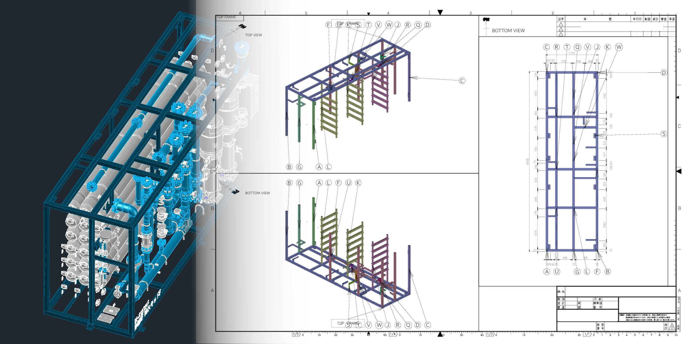
Post cleanup and part connection tracing, with the automagically setup viewport camera angles.
4) Module connectivity tracing
Starting from the frames, we needed to find the parent module (the first part connected to the frame) and then trace every recursively connected part using geometric proximity checks. A complication was that some solids represented "standalone components." We addressed this by merging solid entities whose required extended-data fields matched—resulting in correctly grouped parts and clean, uniform visualization (including consistent coloring of connected sets).
5) Transforming 3D annotations from model space to paper space
This was one of the most frustrating—and ultimately satisfying—milestones. We needed 3D "bubble" annotations to appear in paper space, with arrows pointing to the correct paper-space mapped locations originating from 3D model coordinates. The result: annotations that remain accurate and readable in the exported PDFs.
6) Grid-like dimensioning of frames and drilled parts
The frames required dense linear dimensions to describe cross members and module locations in top/bottom views. Because dimension text becomes cluttered quickly, we had to make smart placement decisions to keep drawings packed but readable, without sacrificing manufacturing precision.
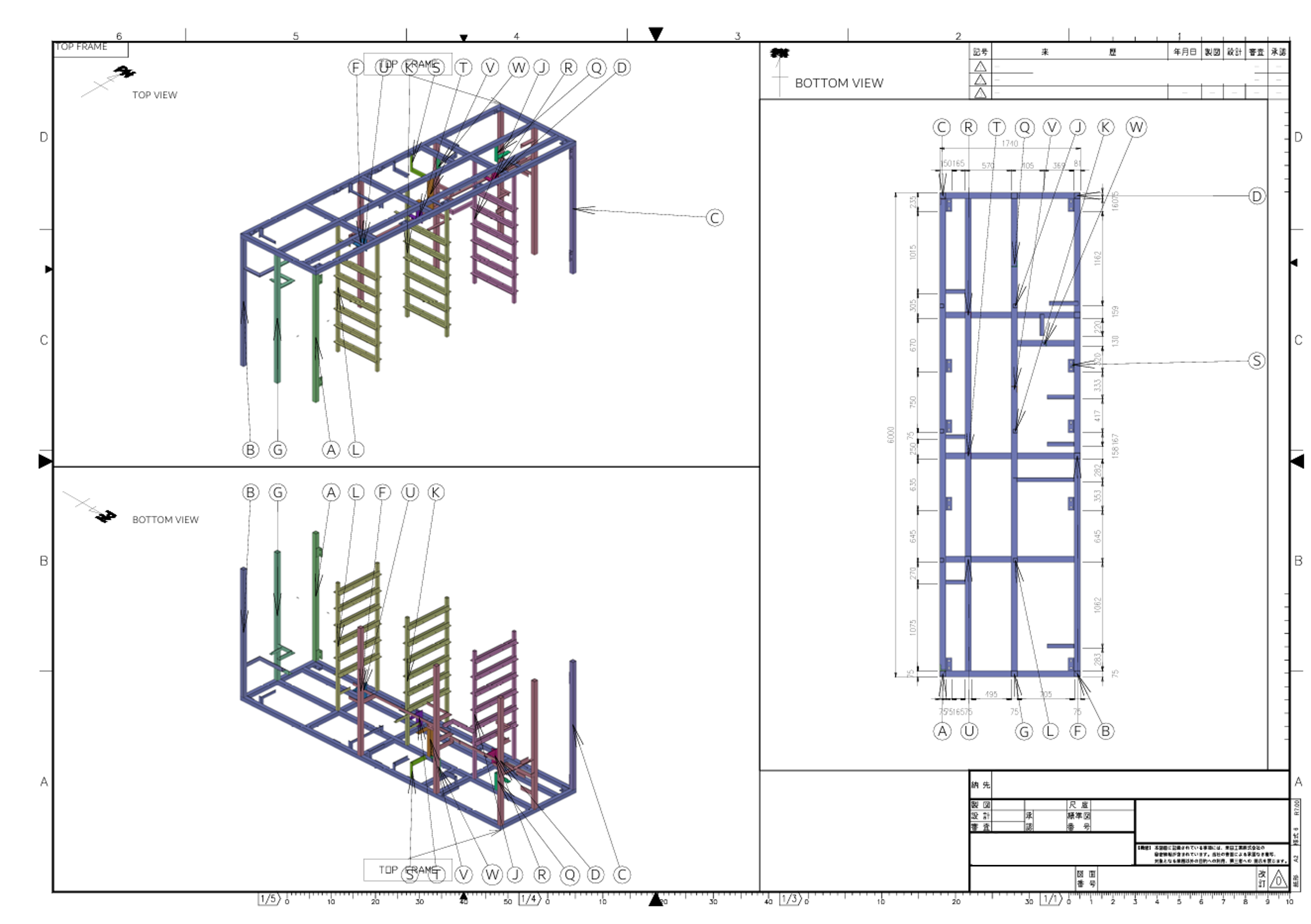
Top frame connections traced with detailed top view dimensioning of parent module connection locations.
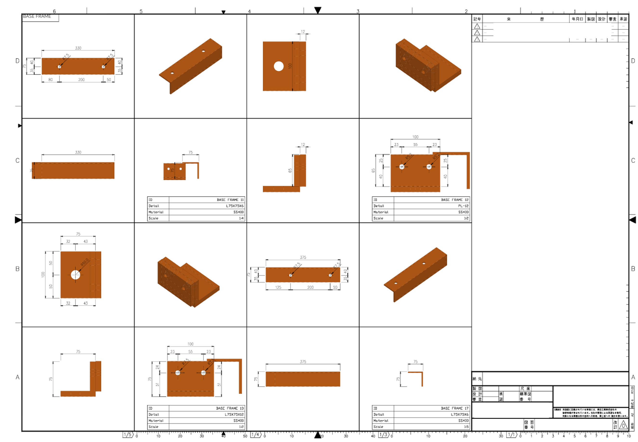
Single drilled part PDF exports with bill of materials data.